
Concentrator
Module: Utilities
Overview
The SBN Concentrator is a 32bit Windows application that concentrates data signals from alarm receivers and forwards them to SBN Server host(s) via SBN Frontend application(s). The SBN Server host(s) interprets the data signals and, if required, presents the data signals to an alarm monitoring dispatch agent.
Concentrators are typically installed in pairs on separate computers where they are configured to provide fail-over redundancy for each other. Each Concentrator (pair) may support up to 128 alarm receivers. You may use unlimited sets of Concentrators with the SBN system; this enables Concentrator support for even the largest organizations.
Concentrators are typically located at the same location as receivers, which may be remote from the SBN server location. Concentrators have the ability to be daisy-chained, if required, to permit organizations with remote receiver sites to consolidate their signal data, providing cost effective data communications.
Concentrators support both serial data & TCP/IP connectivity. Any Windows-recognized �COM� port, including third party �multi-port� adapter cards, can support serial input. TCP signals may be received from any available TCP port.
The SBN Concentrator design is extremely versatile. It supports most known commercially-available alarm receivers and many proprietary receivers, including several bi-directional systems where appropriate data signals are transmitted back to the receiver. Support for additional receivers is usually accomplished easily with knowledge of the communications data protocol.
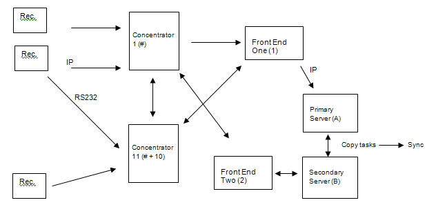
The following chart shows the Concentrator's role in the flow of alarm signals into SBN.
This document covers the following topics:
Installing Concentrator Software
File Descriptions - Concentrator
Creating the Concport_xx.txt Files
Configuring the Concentrator Software
Entering Error Messages into Zone Types
Entering Receiver CIDs in Data Entry
Requirements
The SBN Concentrator requires a 32-bit or 64-bit Intel-based MS Windows XP or higher operating system. IBS recommends that the system OS be as up to date as possible for security and OS patching purposes. The speed and memory required for the Concentrator are sufficient on any newer machine, as the application has small memory and processor footprints. While the Concentrator application and configuration files take less than 20MB of hard drive space, IBS recommends at least 5GB of space available for log files. If you need com port expansion, install and fully test any serial expansion cards and Windows drivers before installing the SBN Concentrator.
After you install and configure the Concentrator, it will operate without user interaction. If you are installing the Concentrator at a remote location, IBS advises you to provide network access to the PC using PC Anywhere, RAdmin, or similar commercially available products. This enables you to perform remote diagnostics, if necessary.
Note: If you enable the debug feature, the Concentrator logs all signals it receives as an output file. When the debug feature is on, you should check disk space daily on the Concentrator machine to keep it running smoothly.
Warning: Remote access accounts cannot ever be logged out. If the remote session is closed, the Concentrator and Frontend will shut down. Be aware of Windows timeout settings on sessions, so that if a user is not connected for a designated period of time, Windows automatically closes the session regardless of any running applications or activity.
Operational Overview
The Concentrator application contains several windows. During normal operations you can use these windows for informational and statistical purposes. In addition, the Concentrator application contains several utilities that you can use during initial setup and signal communication diagnostics.
There are two modes in which the Concentrator acknowledges signals from receivers. Define the mode you want to use in the ImmAckAlarm field of the Config2.txt file.
Normal Mode: The Concentrator acknowledges each alarm only after the signal is inserted into the immediate queue. This mode is very safe but inefficient if you have many signals coming in.
Acknowledge Immediately Mode: The Concentrator acknowledges each alarm immediately, not waiting for confirmation that the signal was successfully inserted into the immediate queue. This allows the receiver to send another signal. This is the most efficient mode to use if you have many signals coming in.
If a communication failure occurs between the Concentrator and the host (SBN server), you can manually acknowledge signals from the Concentrator. (See Getting Alarm Details.)
Installing Concentrator Software
Use the following steps to install the Concentrator:
1. Select setup.exe from the appropriate directory.
‰ The Install Shield will open.
2. Follow the directions in the Install Shield to install the Concentrator and create all necessary files.
l config.txt file. For more information, see Config.txt.
l config2.txt file. For more information, see Config2.txt.
l errorribs.txt file. For more information, see Erroribs.txt.
l messages.txt files. For more information,
see Messages.txt.
Copy messages from the SBN.exe directory after you have logged in to your
server. This will guarantee that all of your company-specific translations
are visible.
l GmtOffse.dat files. For more information,
see GmtOffse.dat.
These files contain the daylight savings information from your server.
l concport_xx.txt files. For more information, see Concport_x.txt.
Note: Put all the executable, configuration, and log files for one Concentrator in a separate directory from files for other Concentrators and programs.
Note: Do not set a Concentrator to start automatically when the computer starts unless you use Windows XP. If you do not use XP, setting the Concentrator to auto-start may cause two copies of the same Concentrator to run, generating error messages.
File Descriptions — Concentrator
The following table describes the files in the initial Concentrator window.
File name |
Description |
SBN_conc.exe |
Main program file (installed with Setup program) |
config.txt |
Main Concentrator definition file, in plain text format (installed with Setup program). O This is a read-only file. |
config2.txt |
Main Concentrator configuration file, in plain text format (installed with Setup program). O Edit this file before you run the Concentrator for the first time. |
erroribs.txt |
Receiver communication protocol definitions. O This file contains the standard protocol definitions for each receiver type and normally need not be altered. |
alarm.log |
Alarm log file, dynamically created by the application - size is defined in config2.tx - LOGSIZE parameter. |
hqueue.dat |
Host transmit queue. dynamically created by the application - size is defined in config2.tx - HOSTSIZE parameter. |
GmtOffse.dat |
GMT and daylight savings offset information from your server. |
messages.txt |
SBN-provided file that defines various dynamic features of the windows (including label text and translations). Copy messages from the SBN.exe directory after you have logged in to your server. This will guarantee that all of your company-specific translations are visible. O Do not edit this file. |
concport_x[x...].txt |
Plain text configuration files; one required for every �port� used by the Concentrator. Typically, you will need one file for each receiver plus three additional files for the ports used for communication between host and other Concentrators. O Files must be named concport_1.txt, concport_2.txt, etc. O Where n... in concport_n[n...].txt is the logical Concentrator port used to connect the external equipment (receiver etc.). |
Concentrator Setup
Configure the Concentrator in two main sections to suit local requirements:
Basic global options
Note: These are defined in the config2.txt file.
The communication and functional definition for each device (receiver, etc.) connected to each Concentrator port
Note: These are defined in concport_x.txt files; one file for each connected device.
The following describes each Concentrator file and how you should configure it, if necessary.
Config.txt
Config.txt is a read-only file. It is not used directly by the Concentrator.
Config2.txt
Config2.txt is an editable file. You should edit this file before you run the Concentrator for the first time. Once you run the Concentrator, the file becomes read-only. If you need to make changes, you will need to restart the Concentrator before they take effect.
Field/Column Descriptions — config2.txt
The following table describes the fields present in the config2.txt file and displays example values to set in those fields.
Field |
Example Value |
Description |
Name |
01 |
Concentrator ID. O When using a Primary/Backup Concentrator pair, the IDs should differ by 10. For example, ID=03 (Primary) connects to ID=13 (Backup). O Examples: |
Company |
0 |
Identifies the company. IBS assigns your number. l 0 = IBS Warning: Do not change your IBS-assigned company number. |
Headername |
IBS |
The header name. The last 3 characters of the brheader.xxx file. O Depreciated; used only in the non-GUI Concentrator version. O Remains in the file for backward compatibility only. |
HOSTSIZE |
2000 |
Number of signals that may be buffered by the Concentrator before the signals are discarded. Note: This is used in the event that the Frontend(s) goes down; this is the number of signals that the Concentrator stores to send to the Frontend(s) when it comes back up. |
LOGSIZE |
20000 |
Number of log records recorded before being overwritten. O Log size should be at least twice the host size. O A LOGSIZE of 10,000 equates to a file size of approximately 2.6Mb. O The alarm.log is a FIFO (first-in, first-out) file; once it is full, it discards the oldest signal logs when it receives a new signal log. |
Relay |
000 |
Optional. If used, it is the port value that the relay adaptor card uses. Use value ’000’ if no relay card present. Relays:
O The port address must be between 512...1024. O Ports are normally specified in hex; addresses are normally specified in decimal. O To signal that the backup Concentrator is offline, make a connection to relay #3. Normally, this will be on, but off when offline. |
PrinterPort |
0 |
Identifies the printer port to which the Concentrator connects. Values can be from 0...3: l 0 = no printer, or a serial port is being used for a printer l 1...3 = corresponding printer ports. For example, 1 = LPT1; 2 = LPT2; 3 = LPT3. |
ErrorACC |
ZREC |
Specifies the SBN CID account used for receiver errors. Constructs the error account as ZRECnnmm.
O An alternative may be ErrorACC = RCVR. This will be the prefix of the CID that generates when an error signal comes in from a receiver. This error signal means the receiver has stopped communicating with the Concentrator. Operators should get supervisor approval before clearing a receiver error alarm. |
TempPhoneZone |
|
Special customer-specific option; no functionality in SBN. |
ImmAckAlarm |
0 |
Defines when the Concentrator will acknowledge alarms; used for higher throughput.
|
RemoteConc |
0 |
Identifies the Concentrator as a remote Concentrator.
|
IOCTLByte |
1 |
Identifies the byte number of the read IOCTL block; used on some brands of multi-port serial boards.
|
IOCTLBit |
5 |
Identifies the bit number of the read IOCTL byte; used on some brands of multi-port serial boards.
|
SuppressTOUT |
00 |
Identifies if the Concentrator monitors for timeout.
|
SuppressPRN |
00 |
Suppresses printer output if the monitored port fails. A failure is when the port goes offline, or when the DSR is lost.
|
HostQueueLev1 |
60 |
Quantity of signals required in Host Queue before relay is activated; has no effect if relay not present. |
HostQueueLev2 |
60 |
Quantity of signals required in Host Queue before relay is activated; has no effect if relay not present. |
InitProg |
0 |
Depreciated; used in the character version only. Retained for backward compatibility. Defines the initial window.
|
PasswordLevel |
0 |
Depreciated; used in the character version only. Retained for backward compatibility. Defines the default password.
|
TimeZone |
CST |
Identifies the default time zone for the Concentrator. Value must match a valid time zone in SBN. Value used in processing signals received from Concentrators in various time zones and includes daylight saving offsets established in the host server in program #1739 Time Zones. A GmtOffse.DAT file is required in the same directory as the Concentrator executable program. |
Erroribs.txt
Erroribs.txt is an editable file. It contains one row for each supported (receiver) device and is only applicable if you connect a receiver that uses serial data.
Usually you will not need to edit this file. However, some receiver manufacturers allow you to change the receiver defaults to another value. If your company has used this feature and changed the receiver values from the default STX or ETX values, you must modify the values in this file. The receiver STX and ETX values must match erroribs.txt.
Any changes that you make to erroribs.txt become effective after restart.
Example of an erroribs.txt file
***** LINE TYPES *************TY*NO*STX*ETX*OK*Comment/Examples*************
ITI IT
10 010 013 OK X '121Y1234Y011A'
FBI FB
11 000 001 OK X '62 0355 1555 5555 1'
ADEMCO 685 AD
13 010 013 OK Combined Ademco
RADIONICS 6500/6000 RA
14 000 020 OK '1502 5900 A E'
Field/Column Descriptions — erroribs.txt
The following table describes the fields present in the erroribs.txt file and displays example values to set in those fields.
Field/Column |
Description |
Receiver name |
Name of the receiver type |
TY |
Two-character receiver ID; designated by IBS; used in alarm translations. |
No |
Receiver number designated by IBS. |
STX |
Decimal STX (Start of Message character) block. O If you do not specify a character to identify the start of a block, the character will default to 000. O If you specify a character to identify the start of a block, all blocks must start with that character. |
ETX |
Decimal ETX (End of Message character) block. O If you do not specify a character to identify the end of a block, the character will default to 000. O If you specify a character to identify the end of a block, all blocks must end with that character. O Values 254 and 255 are reserved for special cases and may not be changed. |
OK |
Indicates OK when tested by IBS. |
Comment/Examples |
Free-form text comments and/or examples. |
Hosts_cnts.txt
Status text file that indicates the number of signals queued in the concentrator. Line 1 contains the date / time. Lines 2, 3, and 4 contain the number corresponding to the display alarm screen.
Receivers
Currently, the Concentrator supports the following receivers/format types:
ADEMCO (Ademco 685, Contact ID)
ALARM FORCE
ALARM NET
ARITEC TAC-90 MODIF
ATLAS
AUDIOLITE
BOSCH MODEM 4
CARE NET
CELLULARM
COMPUTEC
DCX
DEBUGGER RX
DERIVED CHANNEL 1
DM8 DOMITECH
DMP SCS-q
DMP SCS-VR
ELEKTROLUX ETM
EMERSON
FBI
FRANKLIN
HSL 1
HSL PRN READER
IBS GSM
IEI E6800
INFRANET
ITI
KELTRON
MC II
MORSE POLLING
MULTICOM
OSBORNE HOFFMAN
OzVision
POLLING MACHINE (Datavision)
PRO-COM EXTENDED
RADIONICS 6500/6000
RC-4000
RECEIVER TEST
ROBOFON
ROBOFON RBM-600
SAFECOM
SCANCOM
SDN SMS
SDS
SEABOARD RF
SECOM
Note: Signals with Event 28 and zone like HEARTBEAT will now be acknowledged and not sent to ALGEN.
SECURITEL
SESCOA 3000
SIA
SILENT KNIGHT 9000
SMART PRINTER
SPC-5000 MORSE POLLING
SURGARD MLR 2000
SURGARD SIA (Contact ID)
TAR-200 AUDIOLITE
TPS F1
VERITECH V300
VIGILANTE FIRE PANEL
WESTEC
Note: In IP-based configuration, set up IP from the receivers to one Concentrator (primary or backup) and RS232 cables from the receivers to the other Concentrator, so that if one method fails to send a signal, the other sends it.
Alarm.log
Alarm.log is a read-only file. It is initially created by the Concentrator program on first startup to the size defined in config2.txt. It is a FIFO (first-in, first-out) data file of the last x signals processed. The Concentrator uses alarm.log to produce a �Log List� and produces statistical reporting in �Load Statistics�. If communication fails with the host server, alarm.log buffers signals.
When you choose the Log List button in the Concentrator window, you may right-click on the list of logged signals and choose Export. (This may be helpful when troubleshooting.)
Hqueue.dat
Hqueue.dat is a read-only file. It is used by the Concentrator to buffer signals currently processing and awaiting confirmation from the host that they were successfully received.
GmtOffse.dat
GmtOffse.dat is a one-time-only editable file. It is used by the Concentrator to determine time offset calculations between the local time and the host server base reference time.
Messages.txt
Messages.txt is a file provided by IBS. It contains words displayed in the Concentrator windows, providing custom and language translation capability. Copy messages.txt from the SBN.exe directory after setup.
The messages.txt file is found in the following locations:
Windows XP
%USERPROFILE%\Local Settings\Application Data\IBS\<ProgramName>
C:\Documents and Settings\<username>\Local Settings\Application Data\IBS\<ProgramName>
Windows 7
%USERPROFILE%\AppData\Local\IBS\<ProgramName>
C:\Users\<username>\AppData\Local\IBS\<ProgramName>
These locations should always be writable but if not, the following rules explain what should happen.
After the user logs into SBN:
If the messages.txt file does not exist, SBN creates it in the locations above.
If SBN is unable to create the file in the above directories, then SBN reads messages from the database and stores them in memory after the user logs in.
Before the user logs into SBN:
Messages may be read from the messages.txt file. However, if the file does not exist, then messages will be read from a string table resource in the SBN.exe. This will avoid the error 'messages.txt file not found' that prevents the user from logging in.
If the user selects View > Options from the SBN Main Menu before logging in, a new language may be selected and messages will be read from the messages.txt file mentioned above. If the file doesn't exist, an error dialog appears indicating that the file was not found but this will not prevent the user from logging in. SBN reads messages from the string table resource as mentioned above.
Concport_x.txt
Concport_x.txt is an editable file. The concport_x.txt file provides the information required by the Concentrator to fully support the attached receiver device. Concport_x.txt files are also used to provide information on how the Concentrator should support other attached devices, such as other Concentrators, Frontends, and Back-up Hosts that are attached logically to a Concentrator port.
In a typical installation where a Concentrator pair is installed (the second Concentrator providing fail-over redundancy for the primary Concentrator) and where the installation has two hosts (a primary and a backup) the following arrangement would be suitable:
On Primary Concentrator
Concport_01.txt = definition for communications to Primary
Frontend.
Concport_02.txt = definition for communications to Secondary Frontend.
Concport_03.txt = definition for communications to Secondary Concentrator.
Concport_04.txt,Concport_05.txt etc.= definition for communications to
each installed receiver.
On Secondary Concentrator
Concport_01.txt = definition for communications to Primary
Frontend.
Concport_02.txt = definition for communications to Secondary Frontend.
Concport_03.txt = definition for communications to Primary Concentrator.
Concport_04.txt,Concport_05.txt etc.= definition for communications to
each installed receiver (identical to Primary Concentrator files).
When a Windows failover cluster fronts the Front Ends with one virtual IP, each host line carries that virtual IP alone (host,port); see SBN Services Cluster Connection Point.
To achieve full functionality, consider the following:
In general, a receiver sends a signal when it has something to report.
Some receivers send repeated (keep-alive or time) signals to the Concentrator.
Some receivers need special initialization from the Concentrator when they start or restart, or when their connection fails then restarts, to recognize that the Concentrator and communication line are available.
Note: In order to initialize a receiver, the Concentrator reads the DSR line on the serial port, Pin 6 on a 9- or 25-pin standard RS232 cable. When this signal is active, the Concentrator assumes that the receiver is available and, depending on the type, is initialized.
The Concentrator can monitor receivers that send time signals. The Concentrator can generate a timeout alarm if no signals from a receiver are received within a specified period.
Protocols between the Concentrator and a Frontend, backup Concentrator, or remote Concentrator are almost the same because the same type of information is communicated between them.
The Concentrator’s communication protocol has a periodic signal, with acknowledgment once every �X� seconds, as specified in the config2.txt file.
Note: This protocol creates two blocks, one with the signal, and one with the acknowledgment. Each signal sent from a Concentrator also creates two blocks, one with the alarm, and one with the acknowledgment. Consider these blocks when you design wide-area networks, especially switched circuits (MICOM, for example).
Data that a host downloads to a receiver via a Concentrator also creates two blocks on each line.
If your Frontend is on a stand-alone PC, the Frontend uses the SQL library to convert Concentrator messages to SQL requests.
Note: These messages are sent in the SQL internal format and may create more than two blocks for each alarm.
Communication Tests
SBN checks for communication in several ways between the Frontend, receiver, line card, and customer:
Passive timer from Frontend to host.
Note: If host receives no signal, it generates a No Activity signal.
Passive timer for each receiver.
Note: If no signal is received, generates a No Activity signal. If a receiver does not send signals, check the STX and ETX settings in the Erroribs.txt file.
Passive timer for each line card. The timer varies by line card.
Note: If no signal is received, generates a No Activity signal.
Passive timer from installation to host. Defined for each CID.
Note: If no signal is received, generates a Missing Test signal.
Active timer from the Concentrator to the line card.
Note: When 75% of the specified time has elapsed, calls the number for the line card. Panel is Unknown and will generate a Bad Data signal and reset the timer. This feature requires an extra line and modem and may not be passable depending on the logical line setup.
Creating the Concport_xx.txt Files
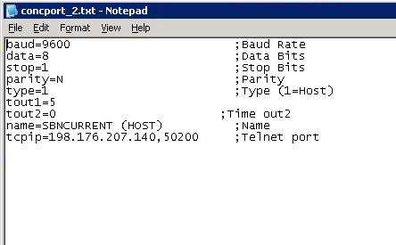
Create one file for each port, where xx indicates the port number. Edit these files, using a standard plain text editor such as Windows Notepad, to make changes to the line setup and logical line definitions.
Warning: Stop the Concentrator before adding receivers or other attached devices. Never add devices to a running Concentrator.
The following graphic displays an example of a concport text file.
Field/Column Descriptions — concport_xx.txt
The following table describes the fields present in the concport_xx.txt file and displays example values to set in those fields.
Field/Column |
Description |
SERIAL COMMUNICATION |
If the attached device will communicate via serial data, the following four rows are required. O Where TCP/IP communication is used these lines must be removed or commented out using a # symbol as the first character in the row. |
baud |
Serial Baud rate between the Concentrator and the device attached to port. O Speeds from 110 to 115,200 supported. |
data |
Data bits. O Values from 5 to 8 supported. |
stop |
Stop bits. O Values of 0 and 1 supported. |
parity |
Communication parity.
|
TCP/IP COMMUNICATION |
If the attached device will communicate via a TCP/IP network, the following row is required. O If Serial communication is used, this line must be removed or commented out using a # symbol as the first character in the row. |
TCP/IP |
Used when the Concentrator will connect to a TCP/IP server. |
STCP/IP |
Used when the receiver acts as a client and connects to the Concentrator. |
type |
Line type; defines the equipment connected to the port. Only pre-defined types are permitted. See Line Types. O Type 40, Debugger RX, receives most signals. It does not generate alarms. It displays the input data in hex format, which enables you to debug new or faulty receivers. Signals will be sent back to the receiver only if the TOUT1 value is different from 0 and the value sent will be chr$(TOUT1), i.e., TOUT1 = 6 = ACK (acknowledged); TOUT1 = 21 = NAK (not acknowledged). |
TOUT1 |
Specifies the time allowed for sending an acknowledge to the receiver. O For initially testing receivers, set TOUT1 to 10. O For receivers, this constant should be the receiver’s internal timeout value divided by 2. For the Host, TOUT1 defines the retry interval for sending alarms to the Host, normally set to 8 or 10. O For the log printer, TOUT1 has no function and should be set to 0. |
TOUT2 |
Timeout value 2. Specifies how long the Concentrator waits for an idle signal from the receiver before the Concentrator generates an alarm. O For initially testing receivers, set TOUT2 to 0. O For receivers that send idle signals, normally TOUT2 is set to twice the interval between idle signals. For example, if the receiver sends idle signals at an interval of 5-10 seconds, set TOUT2 = 20. Then, if the Concentrator receives no signals for 20 seconds, it generates an error alarm. O For receivers with polling capabilities, set TOUT2 slightly higher than the maximum interval between line activity. This enables the Concentrator to detect receiver failures and line breaks. O For the Host, TOUT2 defines the maximum time between alarms sent to the Host. Set TOUT2 lower than the corresponding timeout on the Host. If no real alarms occur, the Concentrator generates alarms against the Host’s error account. O For the log printer, TOUT2 has no function and should be set to 0. |
name |
Description of the receiver. |
lc |
Number of line card blocks; must be followed by the lines below repeated lc times. |
id |
Line card ID from the receiver. |
prefix |
Logical line number for the physical line. You can type up to 13 digits. Type the digits in front of the chip number from the receiver to create a unique CID. O You can use placeholders to specify the length of the CID (at least as many digits as the chip number + 1, but no more than 13 digits). For example, 163_ _ _ _ plus the chip number 928 will result in a CID of 1630928. O Without placeholders, the CID will always be 13 digits long. |
phone |
Phone number connected to the line. This field is read-only unless you define a line setup for the Receiver Test #48. O Two minutes before the TOUT expiration, if the Concentrator has not received a signal, it will call the phone number typed in this field. If the Concentrator contacts the receiver, the receiver will send a special �No Data� message upstream that the program can use to verify that the line is okay. The Alarm generator usually discards this type of signal. |
seq |
Roll over sequence number. The Concentrator uses the roll over sequence number when the load report program generates the distribution of alarms on the different roll over lines. O Hardware determines the roll over lines, and their configuration. O The LIN and # combine to create unique numbers. |
comm |
Free-form comment for the line. |
tout |
Timeout value for this telephone line. The value entered is the number of seconds between signals arriving on the corresponding telephone line. O If the Concentrator receives no alarms within the specified time, including the �No Data� message generated by the outbound call, it generates an error alarm. |
Line Types
The following table displays predefined line types.
Type |
Receiver Name |
1 |
Host connection |
6 |
Backup Host (Manual PC) |
7 |
Backup Concentrator |
8 |
Conc RX |
9 |
Logprinter |
10 |
ITI |
11 |
FBI |
13 |
ADEMCO 685 |
14 |
Radionics |
15 |
Silent Knight |
16 |
Polling |
17 |
Aritec TAC-90 Modif. |
18 |
Robofon |
19 |
Elektrolux etm |
20 |
Franklin |
21 |
MC II |
22 |
HSL 1 |
23 |
DMP SCS-q |
24 |
Veritech V300 |
26 |
SESCOA 3000 |
27 |
Seaboard RF |
28 |
SPC-5000 Morse Polling |
29 |
IEI E6800 |
30 |
Carenet |
31 |
Securitel |
32 |
Scancom |
33 |
HSL Prn Reader |
34 |
SIA |
35 |
Derived Channel 1 |
36 |
Pro-Com Extended |
37 |
Safecom |
38 |
Surgard SIA |
39 |
TAR-200 |
40 |
Debug Receiver |
42 |
Morse Polling |
43 |
RC-4000 |
44 |
Infranet |
45 |
Audiolite |
46 |
DM8 Domitech |
47 |
DCX |
48 |
Receiver Test |
49 |
Westec |
50 |
Keltron |
51 |
Multicom |
52 |
SURGARD MLR2000 |
53 |
Vigilante Fire Panel |
54 |
IBS GSM |
55 |
Osborn Hoffman |
56 |
Secom |
57 |
TPS F1 |
58 |
SDN SMS |
59 |
Alarm Net |
60 |
Smart Printer |
61 |
Alarm Force |
62 |
SDS |
63 |
Surguard MLR 2000 A |
64 |
Emerson |
65 |
Cellularm |
66 |
OZVision |
67 |
Computec |
68 |
ATLAS |
Polling
The Concentrator polls some receivers. For those receivers, use TOUT2 to define timeout errors. Enable active polling by setting the TOUT2 values above 20 seconds. The Concentrator polls at an interval of (TOUT2 value) minus 20 seconds. For example, if TOUT2=60, the Concentrator polls the receiver every 40 seconds. If the Concentrator does not receive a response within 60 seconds, the timeout is signaled as normal.
Polling Signals
The following table lists signals sent by specific receivers.
Type |
Receiver Name |
Signal |
11 |
FBI |
’S’ |
15 |
Silent Knight |
0x14’0000T’0x0D (0x0D=CR) |
42 |
Morse Polling |
’!’ |
44 |
Infranet |
0x02’50’0x03 |
Configuring the Concentrator
Attach each receiver to the Concentrator with a NULL MODEM cable (usually DB25 male to female) to the serial connections on the Concentrator. Some receivers will require a normal cable.
Attach the Concentrator to other Concentrators with
A NULL MODEM cable if your are using a serial connection (usually DB25 male to female)
Note: Configure the pin outs of the NULL MODEM cable according to the following chart:
Pin |
to |
Pin |
1 |
to |
1 |
2 |
to |
3 |
3 |
to |
2 |
4 |
to |
5 |
5 |
to |
4 |
6 |
to |
20 |
8 |
to |
20 |
7 |
to |
7 |
20 |
to |
6 |
20 |
to |
8 |
A standard network cable.
Attach the Frontend to the Concentrator with
A NULL MODEM cable if you are using a serial connection with a 9-25 pin adapter.
Note: Configure the pin outs of the NULL MODEM cable according to the following chart:
Pin |
to |
Pin |
1 |
to |
1 |
2 |
to |
3 |
3 |
to |
2 |
4 |
to |
5 |
5 |
to |
4 |
6 |
to |
20 |
8 |
to |
20 |
7 |
to |
7 |
20 |
to |
6 |
20 |
to |
8 |
The Frontend uses standard serial ports (usually two 9-pin serial ports or one 9-pin port and one 25-pin port) instead of a Serial Interface Board.
A standard network cable.
Attach printers to the Concentrator with
A serial cable if you are connecting to serial cards.
One of the printer ports on the Concentrator.
Configuring the Concentrator Software
Use the following steps to configure the Concentrator software:
1. Create the concport_xx files for all lines.
2. Set up the Line Definitions from the Main menu.
3. Assign the different lines to different pieces of equipment such as
l Printer
l Backup PC
l Backup Host PC
l Frontend
l Various receivers
4. Assign different timeout values to the connections.
5. Set up the CID prefixes used when generating CIDs on the various line numbers on the connected pieces of equipment. Use the same numbering method as the one used on the Host computer to define the CID generation.
6. From the PC, start the Concentrator executable.
Use the following steps to set up the Receiver Error Accounts:
1. On the Host computer, in the CONFIG2.txt file, define the prefix for signals that come from a receiver (for example, ERRORACC=’RCVR’).
2. In Zone Types, program #1733, define possible receiver error messages as zone types. You may also use previously defined zone types for error messages.
3. Define the error messages as zones in your receiver error account.
Note: For more information, see Sample Error Messages.
4. In Data Entry, type the different receiver CID numbers and their respective zones.
Note: For more information, see Entering Receiver CIDs in Data Entry.
Entering Error Messages into Zone Types (#1733)
You can use the Zone Types (#1733) program to define specific zone types to tie to receiver error messages. For example, you may have a zone type TOU for Receiver Line Timeout. You would then tie this zone type to the specific zone in your receiver error account. Other error messages may only require an existing zone type, such as Trouble. Once you have tied the zone type to the zone in the receiver error account, you can then customize the priority and behavior of that particular zone.
Sample Error Messages
The following table presents generically defined error messages. The samples include most messages that receivers would send.
Note: Some receivers have other zones, like CFL for communication failure. See the appendix of each receiver for a list of their additional zones.
Zone |
Error Message |
1 |
Receiver line timeout. Receiver sends this when the TOUT2 timer expires. O See description of Logical Timeout, zones 21-32. |
2 |
Garbage. Receiver sends this after it sends the same unrecognized signal five times. |
3 |
Dead Call. A receiver received a call without a signal. |
4 |
A receiver received a call, but lost the connection before the call was completed. |
5 |
Receiver has an AC power problem. |
6 |
Communication trouble. |
7 |
Tamper on receiver. |
8 |
DSR lost. |
9 |
Printer problems on the receiver. |
10 |
Self-test done. O This usually occurs after a power-up or after someone presses the test button. |
11 |
Bad format. O This message used infrequently; replaced by Bad Data. |
12 |
Bad Data. A value in a normal accepted block is out of the expected range. |
13 |
Receiver has a battery problem. |
14 |
Reset done. This occurs after a power-up. |
15 |
Test button used. |
16 |
No data in message. |
17 |
Data/time set. |
18 |
Message to operator. |
19 |
Unknown alarm. |
20 |
Low priority message to operator. |
301 |
Phone line times out. The receiver sends this message when the timer on a logical line expires. O Phone line timeout is different from zone 1, receiver line timeout. Zone 1 is for the whole receiver, but these zones are for each of the 12 possible logical lines on a receiver. |
401 |
Line problem. A receiver has a problem in one of the phone lines. |
501 |
Phone problem; normally due to a faulty line interface card. |
100 - 200 |
Miscellaneous messages. O Defined for HSL error message. See HSL manual for response codes 1 - nn which translate to 101 - 1nn. |
Entering Receiver CIDs in Data Entry
Receiver CIDs in Data Entry allow you to take full advantage of SBN functionality to monitor your receivers. Once you have entered the CID, you can specify zones for each error and specific action plans that can email, page, or fax relevant error information, just as SBN does for conventional alarms. You can also enter specific instructions to your operators for each error in the action plan tied to the zone for the error.
Use the following steps to create a Receiver CID in Data Entry (program #559):
1. In Service/Data Entry, choose New Record.
2. Type the Receiver CID manually, using the naming convention in the config2.txt file.
Note: For example, a CID for a receiver attached to Concentrator 01 and logical line 07 could be RCVR-0107.
Note: Define all remote receivers in the same manner.
3. Complete the required fields:
l CID
l Panel
l Test Int
l ID
l Ins No
l Dealer ID (No label)
l Phone
l Name (No label)
l Time Zone
l Mon Stat
l Inst Date (No label)
Note: Your required fields may include additional fields that have been defined by your tool-tip color.
4. Choose Save Record.
The Concentrator Window
The following graphic shows the main window of the Concentrator program. The window displays a list of receivers.
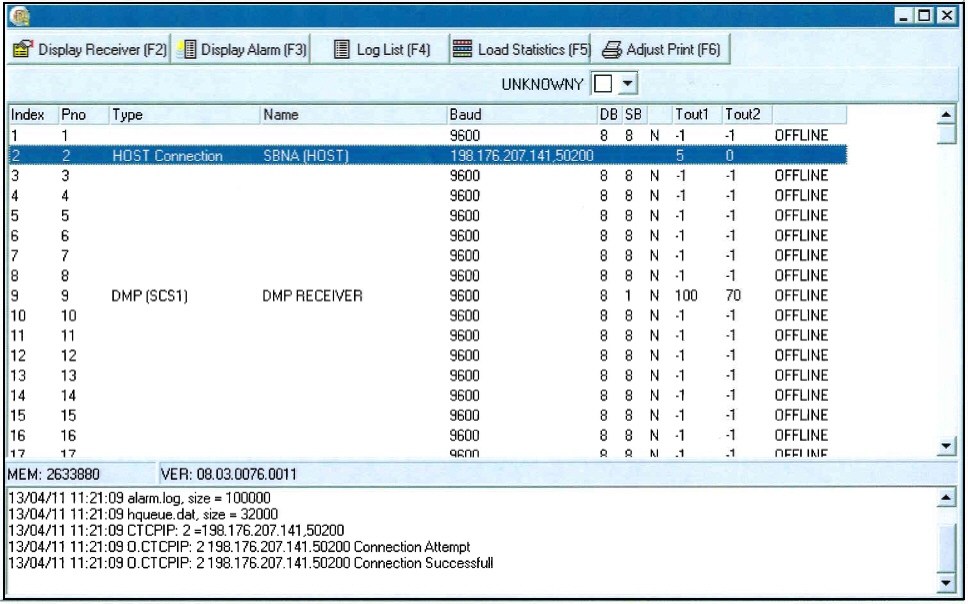
Field/Column Descriptions
The following table describes the fields and columns used in the main window of the Concentrator program.
Field/Column |
Description |
Background Color |
Select the background color of the window. O When you choose black as the background, the text will appear in yellow. |
Index |
Port Number. O Index 1 = Comm 1 if you use serial-based connectivity. |
Pno |
Port Number. |
Type |
Receiver type. |
Name |
Receiver name. |
Baud |
When configured as RS-232, this shows the baud rate of the ports that could be obtained by the Concentrator. When configured as IP, this shows the IP address and port number. |
DB |
Data bits. |
SB |
Stop bits. |
Parity |
Parameter for RS-232 connection. |
Tout1 |
Time out value 1. Specifies the receiver’s status when handling an alarm until the host acknowledges it. For receivers, this constant should be the receivers internal time out value divided by 2. O Set to 10 when initially testing a receiver. For the Host, TOUT1 defines the retry interval for sending alarms to the Host, normally set to 8 or 10. O TOUT1 has no meaning for the log printer and should be 0. |
Tout2 |
Time out value 2. This tells the concentrator how to treat idle signals. If no time out handling is possible, set to 0. Time entered specifies the delay to wait for an idle signal before signaling an error. Set to 0 when initially testing a receiver. If the receiver is sending idle signals, normally set TOUT2 to twice this interval. For receivers with polling capabilities, TOUT2 should be slightly higher than the maximum interval between line activity. This allows the concentrator to detect receiver failures and line breaks. If the receiver does not support this feature, TOUT2 should be 0. For example: TOUT2=20 If no signals are received for a 20 second period, then an error is generated. (TOUT2 will typically be twice the receiver’s idle period, so if the receiver is sending idle signals at an interval of 5 to 15 seconds, TOUT2=20 would be fine.) For the Host, TOUT2 defines the maximum time between alarms sent to the Host. If no real alarms are available, alarms are generated against the Host’s error account. TOUT2 should be defined lower than the corresponding time out on the Host. If the constant is 0, these alarms are not generated. For the log printer, TOUT2 has no function and should be 0. |
Status (No label) |
Indicates whether a port is online or offline. (Offline ports have not been configured in the concport_x.txt file.) |
Getting Receiver Details
Use the following steps to view receiver details:
1. In the main window of the Concentrator program, highlight the receiver for which you want to view details.
2. Select Display Receiver.
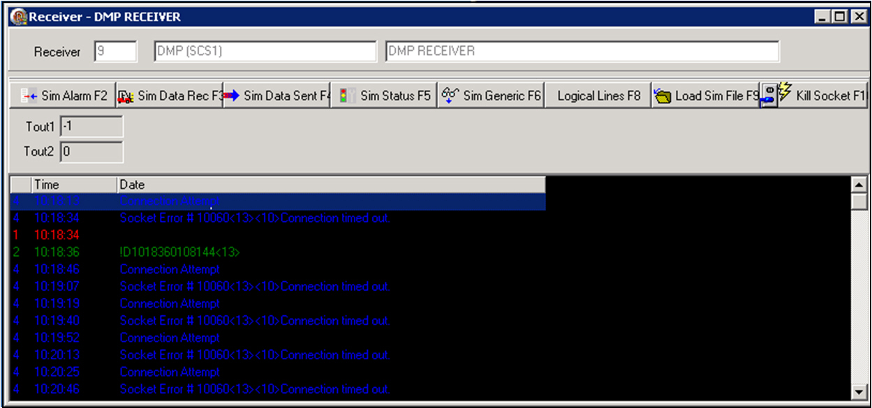
‰ The receiver window opens, displaying details of the receiver you selected. The window displays each message the receiver has received or sent.
Note: The received messages appear in red text; the sent messages appear in green text. Information about the signals appears in blue text. Status messages appear in dark red text.
Examples of sent messages include 6 (signal acknowledged) and 21 (signal not acknowledged).
Troubleshooting Notes: An incorrect End of Transmission (EOT) character in a signal sent by a receiver may prevent the Concentrator from receiving the signal.
Use the Kill Socket button in this window to reset the connection between the selected receiver and the Concentrator.
Note: The threading model for the Concentrator has been changed, with a separate thread handling connections. This improves performance when the Concentrator attempts to reconnect to receivers.
Field/Column Descriptions
The following table describes the fields and columns used in the Receiver window.
Field/Column |
Description |
Receiver |
ID of the receiver. |
Name |
Name of the receiver. |
Description |
Description of the receiver. |
TOUT 1 |
Number of seconds to send an Acknowledged message for a received signal. Note: Any timer with a value of ’-1’ is stopped. |
TOUT 2 |
Number of seconds for the Idle Timer. (After this number of seconds, the Concentrator sends a No Activity alarm if it does not receive a signal from the receiver.) Note: Any timer with a value of ’-1’ is stopped. |
Time |
Time of event. |
Data |
Data associated with event. |
Logical Lines
If you need to create an alarm ID longer than the four-digit receiver CID, you may do so using a line card mask by choosing the Logical Lines button in the Receiver Details window. SBN replaces the underscores in the mask with the four digits of the panel (chip) number.
The following graphic displays the Receiver Details window after you press the Logical Lines button. The window displays the mask for each line card defined in the concport_x.txt file.
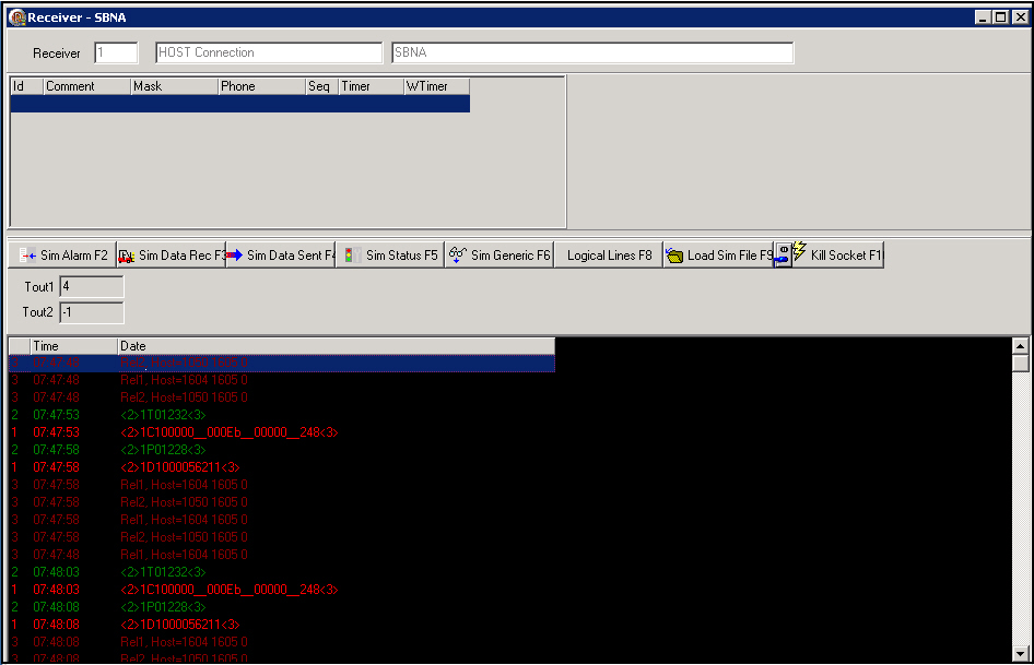
Column Descriptions
The following table describes the columns used in the Logical Lines display of the Receiver window.
Field/Column |
Description |
ID |
ID of the line card. |
Comment |
Line card comment text. |
Mask |
Line card mask. SBN replaces the underscores with the four digits of the chip number. |
Phone |
Phone number that the modem calls to prompt a signal on a receiver that has stopped sending signals. (Generally no longer used.) |
Seq |
Line card sequence number. |
Timer |
How long to wait for signals from the line card. |
WTimer |
How long to wait for signals before the modem calls the number in the Phone column to prompt a signal on a receiver that has stopped sending signals. (Generally no longer used.) |
Getting Alarm Details
Use the following steps to view alarm details:
1. From the main window of the Concentrator program, highlight the receiver for which you want to view alarms.
2. Select Display Alarm.
‰ The Display Alarm window opens, showing signals currently processing.
The following graphic shows the Alarm Display window in Host mode.
In Manual mode, you can acknowledge each signal manually using the Acknowledge button. When you return to Host mode, you can choose to discard or send pending signals.
Note:
All alarms appear in red, yellow, or green text. Alarms initially appear
in red text and end in green text.
Red = Unacknowledged alarms
Yellow = Alarms that have been acknowledged in manual mode
Green = Alarms sent to the Host.
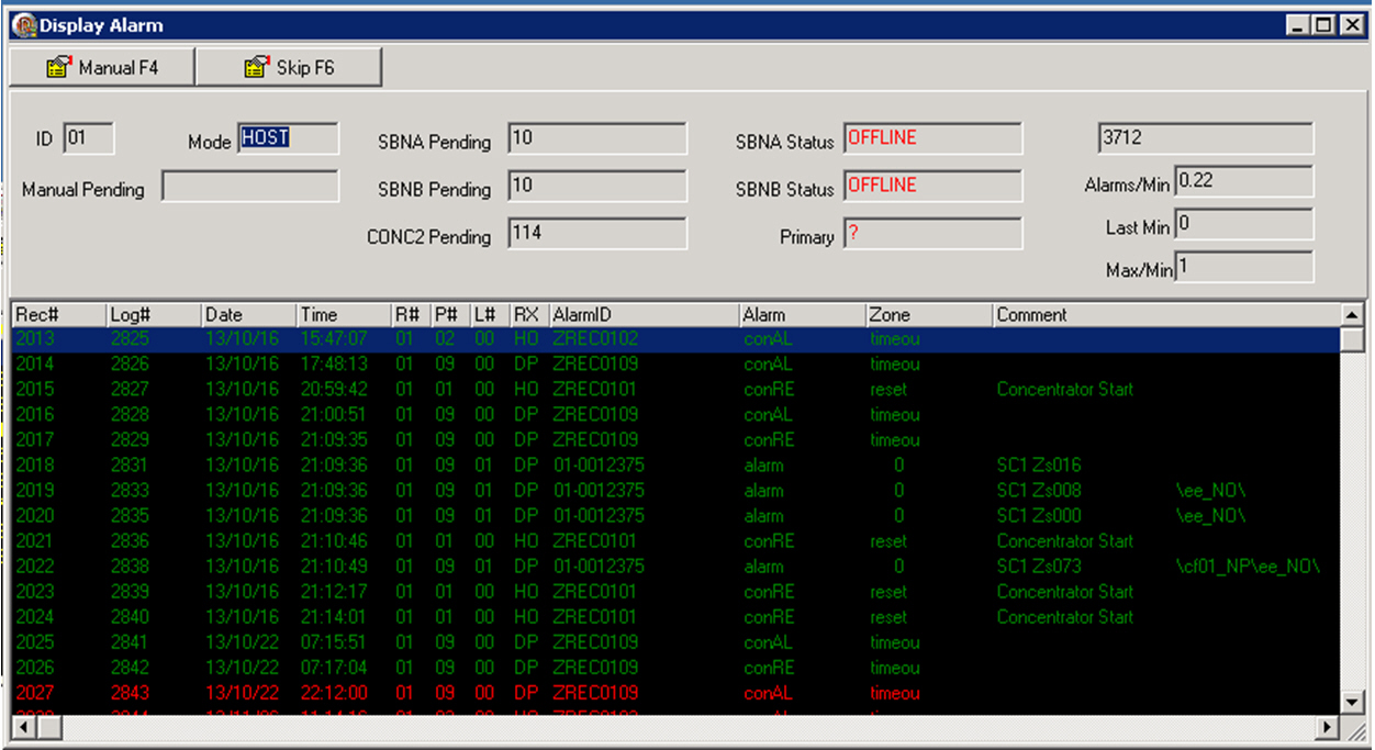
Note: Use the Skip button only when instructed by IBS to skip the first received signal in very rare instances.
The message "Connection refused" means the Frontend is down.
Field/Column Descriptions
The following table describes the fields and columns used in the Display Alarms window.
Field/Column |
Description |
ID |
ID number assigned to this Concentrator in the config2.txt file. |
Mode |
Displays currently selected mode. |
Manual Pending |
In Host mode, this field remains blank. In Manual mode, this field contains the number of alarms not yet shown on the window. |
SBNA Pending |
Displays the number of alarms pending in the SBNA host. |
SBNB Pending |
Displays the number of alarms pending in the SBNB host. |
CONC2 Pending |
Displays the number of alarms pending in the CONC2 Concentrator. |
SBNA Status |
Displays the current status of the SBNA host. |
SBNB Status |
Displays the current status of the SBNB host. |
Primary |
Displays the current primary server. |
Counter (No Label) |
Displays the number of alarms run through the Concentrator since it was last turned on. |
Alarms/Min |
Average number of alarms received per minute; calculated over the last 10 minutes. |
Last Min |
Number of alarms received within the last minute. |
Max/Min. |
The maximum number of alarms received, per minute, for the last 10 minutes. |
Rec # |
Sequence number. |
Log # |
Record number in local log for debugging purposes. |
Date |
Date on which the signal was received by the Concentrator. |
Time |
Time at which the Concentrator received the alarm. |
R# |
ID number assigned to this Concentrator in the config2.txt file. |
P# |
ID number of the Concentrator from which this alarm came. O If the alarm came from this Concentrator, the P# will be the same as the R#. If the alarm came from a different Concentrator, the P# will be different from the R#. |
L# |
Line number on the Concentrator from which the signal/alarm came. |
RX# |
Abbreviated name of the receiver on which the alarm originated. |
Alarm ID |
ID, up to 13 digits. |
Alarm |
A 5-character description of the alarm type. See table of alarm types below. |
Zone |
Identifies the alarm zone received or abbreviated description of any non-customer alarms received. For example, timeout, garbage, com. |
Comment |
Displays any comment sent to the Host. |
Alarm Types
The following table describes both normal and error alarm types that appear in the Display Alarm window.
Note: These alarm types also appear on the log printer.
Type |
Internal Display Name |
Full Name |
A |
Alarm |
Alarm |
B |
Resto |
Restore |
C |
Batt |
Battery |
D |
Cance |
Cancel |
E |
Super |
Supervisor |
F |
Bypas |
Bypass |
G |
Troub |
Trouble |
H |
Open |
Opening |
I |
Close |
Closing |
J |
Log |
Log |
K |
EXTCL |
Late Close |
L |
EXTCL |
Late Close |
M |
PerCl |
Perimeter Close |
Q |
Duress |
Duress |
R |
SpecA |
Special - Alarm |
S |
Prev |
Previous Event |
T |
Miss |
Miss |
V |
RecAL |
Receiver Alarm |
W |
recRE |
Receiver Restore |
X |
ConAl |
Concentrator Alarm |
Y |
ConRe |
Concentrator Restore |
Log List
Use the Log Listing functionality to view raw and prefixed signals during a determined time period.
The following graphic displays the Log List window after you press the Log List button with set parameters.. The window displays the raw and the prefixed signal for each Alarm ID..
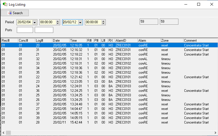
Field/Column Descriptions
The following table describes the columns used in the Logical Lines display of the Receiver window.
Field/Column |
Description |
Upper Pane |
|
Period - Start Date |
Enter a start date for how far back to go. |
Period - Start Time |
In a start time in military format. |
Period - End Date |
Enter an end data for how far forward to go. |
Period - End Time |
Enter an end time in military format. |
Ports |
Enter a concport range. Note: User can place range from 1-N, or place the same number to isolate it to a specific concport file. When a concport range is entered, only the raw signals |
Cyclical Log Fields |
Position in the log file where the log was written. When these fields are the same, the Log List is complete. Log size kept is defined in config.txt file. |
Lower Pane |
|
Rec# |
Receiver number. |
Conc# |
Concentrator where signal landed. |
Log# |
Log number. |
Date |
Date. |
Time |
Time. |
R# |
Receiver number. |
P# |
Concport number. |
L# |
Line number. |
RX |
Receiver type. |
Alarm ID |
Alarm ID |
Alarm |
Type of alarm. |
Zone |
Raw signal. |
Comment |
Reporting format and Event. |
Exporting/Printing a Log List
To Print or Export a Log List after your search is complete, right-click within the returned search criteria windows and select your appropriate option. Selecting Print will load your default printer window.
Selecting export will bring up the Export Settings window where users can select their appropriate settings.
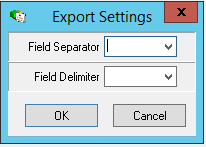
Helpful Hint: Test Servers
It is often useful to configure a test server or two along with Concentrators and Frontends on one computer for testing purposes only. Use the testing environment to shut down various components and observe the changes in signal flow. This helps with troubleshooting should you experience problems with your actual monitoring components. Use the Simulate Alarm button only in the testing environment.
Troubleshooting
The following tips may be useful when troubleshooting communication problems with the Concentrator.
When you choose the Log List button in the Concentrator window, you may search a period of Receiver Log history (on a particular port if you wish). You may right-click on the list of logged signals and choose Export. Then you can put the data into Delphi to aid in troubleshooting.
If a receiver does not appear to communicate with the Concentrator, ping the receiver to verify communication between the two. Likewise, if two Concentrators do not appear to communicate with each other, ping to verify communication.
Each receiver requires a unique IP socket number. If two receivers have the same socket number, they will not function properly.
Concentrator baud rate must match the receiver baud rate.
If a receiver does not send signals, check the STX and ETX settings in the Erroribs.txt file.
An incorrect End of Transmission (EOT) character in a signal sent by a receiver may prevent the Concentrator from receiving the signal.
For problems with a receiver, see the user manual from the receiver manufacturer.
Ports that are displayed as Offline in the main Concentrator window have not been configured in the concport_xx.txt file.
When diagnosing problems, it is sometimes helpful to view alarms on a specific receiver. In Manual mode of the Display Alarm window, you can acknowledge each signal manually. (See Getting Alarm Details.)
In Display Alarm view, "connection refused" means the Frontend is down.
Warning: Remote access accounts cannot ever be logged out. If the remote session is closed, the Concentrator and Frontend will shut down. Be aware of Windows timeout settings on sessions, so that if a user is not connected for a designated period of time, Windows automatically closes the session regardless of any running applications or activity.
Button Functions
The following table displays the buttons, describes the shortcut keys, actions and functionality.
Button |
Name |
Shortcut Key |
Action |
Description |
|
Display Receiver |
f2 |
* |
View details of the selected receiver. |
|
Display Alarm |
f3 |
* |
View signals currently processing on the selected receiver. |
|
Log List |
f4 |
* |
Display a list of logged signals the Concentrator has received. |
|
Load Statistics |
f5 |
* |
Display statistics for the number of alarms received from each logical line number, their distribution in time, and their distribution between roll over lines. |
|
Adjust Print |
f6 |
* |
Adjust date and time of the Last Log Printer. |
|
Sim Alarm |
f2 |
* |
Simulate an alarm record in the Receiver Details window for testing purposes. (Do not use in production environment.) |
|
Sim Data Rec |
f3 |
* |
Places a data received (red text) record in the Receiver Details window for testing purposes. (Do not use in production environment.) |
|
Sim Data Sent |
f4 |
* |
Places a data sent (green text) record in the Receiver Details window for testing purposes. (Do not use in production environment.) |
|
Sim Status |
f5 |
* |
Places a status record in the Receiver Details window for testing purposes. (Do not use in production environment.) |
|
Sim Generic |
f6 |
* |
Places a generic (blue text) record in the Receiver Details window for testing purposes. (Do not use in production environment.) |
|
f7 |
* |
Print data currently displayed in the Receiver Details window. |
|
|
Logical Lines |
f8 |
* |
View line card definitions for the selected receiver. |
|
Load Sim File |
f9 |
* |
Load a saved file of simulated signals for testing purposes. (Do not use in production environment.) |
|
Exit without saving |
esc |
|
Exit without saving changes to selected record. |
|
Save Existing Record |
enter |
|
Save changes to selected record. |









*There are no actions associated with the Concentrator.
Failover Client Connections
Failover client connections are supported via multiple connection endpoints, improving resilience.
Danish ANET Protocol
Danish ANET protocol support was added.
Line-Timeout Restore Handling
Line-timeout restore handling was added.
Modifications and Updates to Concentrator
The following table lists modifications and updates to the Concentrator document.
Mod Number |
Date |
Description |
08.80.00422, 07.80.23231 |
04/07/14 |
Added Bosch Modem 4 to the list of Receivers. |
08.78.09178 |
04/07/14 |
Updated Concentrator Screens images. |
08.80.00423 |
04/23/14 |
Included a notice on the change in the Concentrator threading model. |
07.82.23706, 08.82.09857, 08.81.09805 |
08/25/14 |
Concentrator is compatible with the latest version of XE6 |
N/A |
02/12/20 |
Cyclical Log fields added within Log List pane. |
F1 Help
| Delphi Forms | ubtimezoneprofform |
| Program Numbers | 1739 |